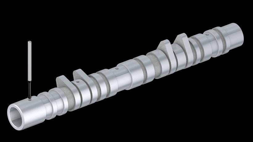
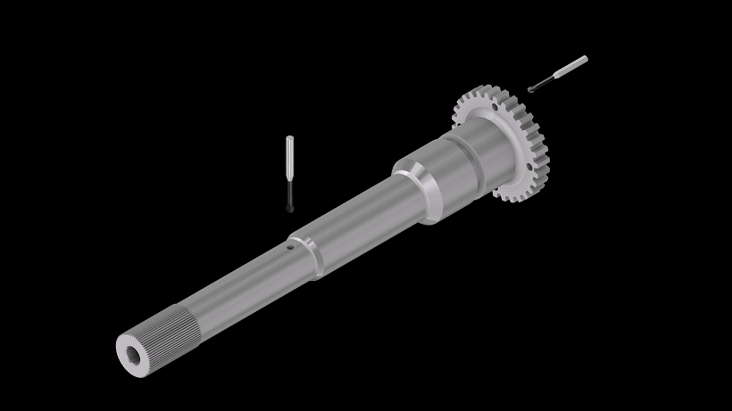
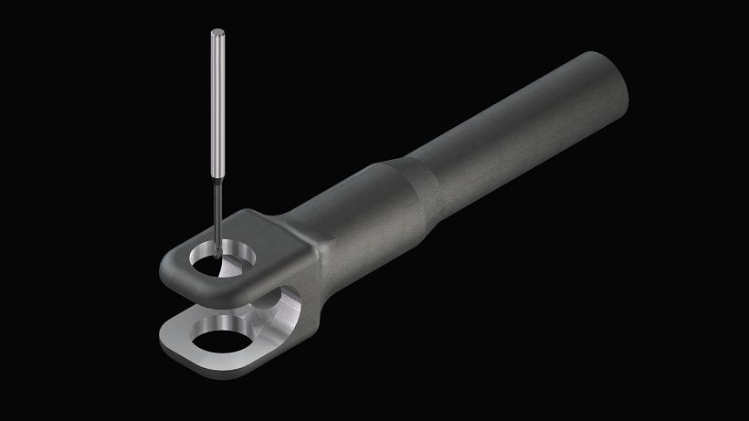
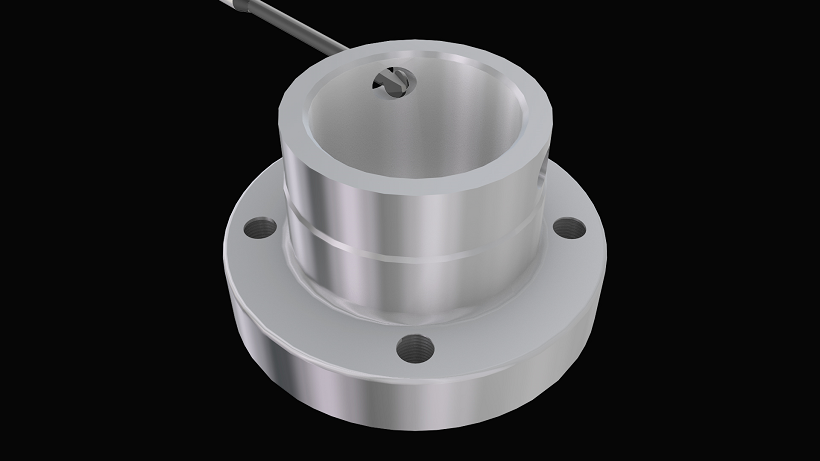
Optimal solution for high-precision deburring of 3D-curved crossholes
This tool can be mounted on machining center (XYZ-axis) or combined lathe (XZY or XZC-axis). 3-axis simultaneous control is required.
 Machining center
 Turn Mill Machine
 Lathe (no live tooling)
 Special machine
 Robot
Robot Rotary tool
 Rotary tool
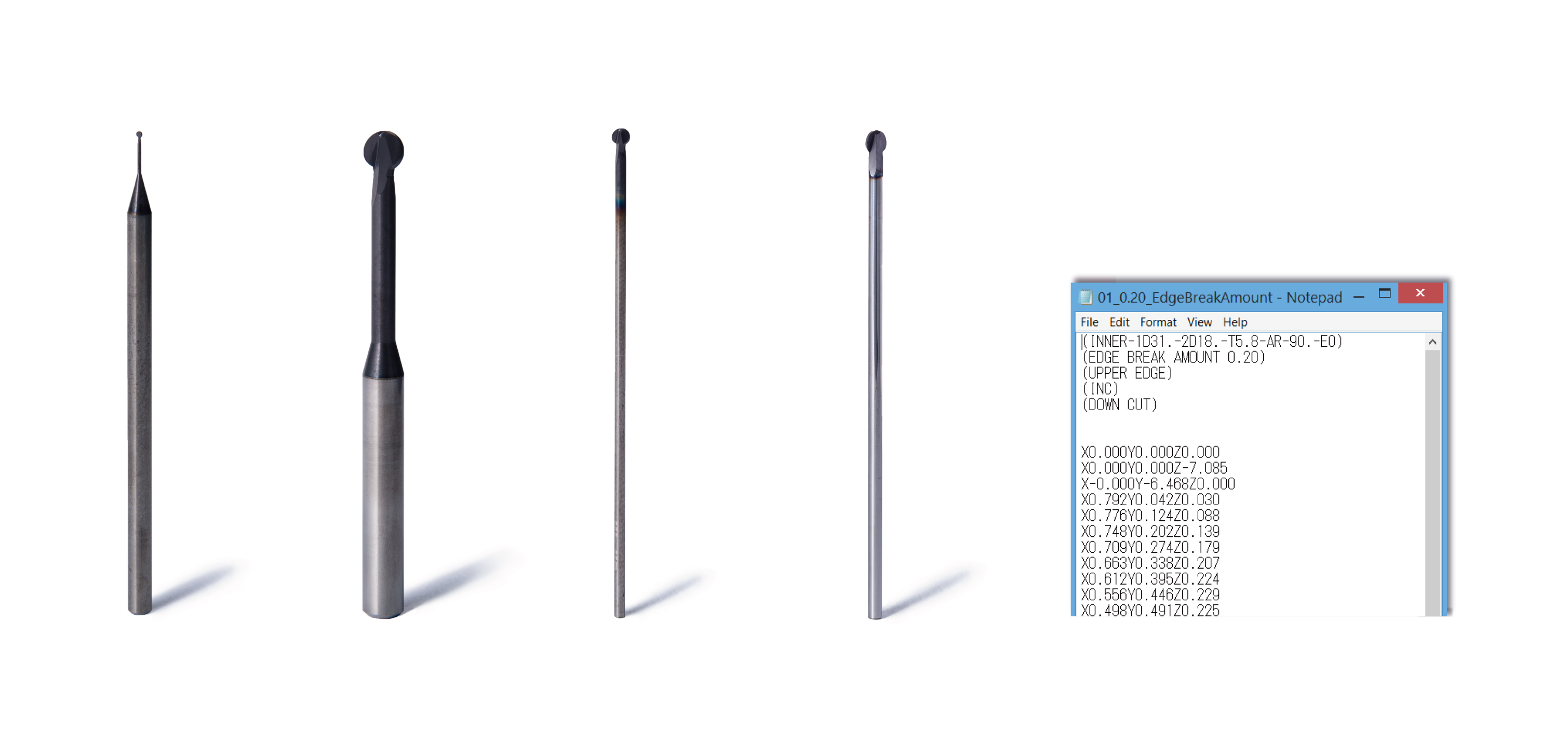
Spherical deburring cutter and Tool Path (NC data set) created specifically for the customer application.
See online “hole-deburring application form” for more details on custom-made Tool Path.
Applicable workpiece materials: Steel, stainless steel, cast iron, superalloys, non-ferrous metals
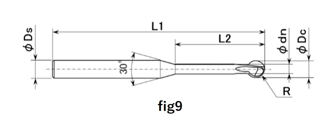
| Product code | Cutter radius R (mm) |
Cutter diameter Dc (mm) |
Neck diameter dn (mm) |
Neck length L2 (mm) |
Overall length L1 (mm) |
Shank diameter Ds (mm) |
Number of blades | Fig |
| XC-08-AS-3F | 0.4 | 0.8 | 0.48 | 3 | 60 | 3 | 3 | 9 |
| XC-13-AS-3F | 0.65 | 1.3 | 0.78 | 5 | 60 | 3 | 3 | 9 |
| XC-18-AS-3F | 0.9 | 1.8 | 1.1 | 6 | 60 | 3 | 3 | 9 |
| XC-23-AS-3F | 1.15 | 2.3 | 1.4 | 7.5 | 70 | 3 | 3 | 9 |
| XC-28-AS-3F | 1.4 | 2.8 | 1.7 | 9 | 70 | 4 | 3 | 9 |
| XC-33-AS-3F | 1.65 | 3.3 | 2 | 10.5 | 70 | 4 | 3 | 9 |
| XC-38-AS-3F | 1.9 | 3.8 | 2.4 | 12 | 70 | 4 | 3 | 9 |
| XC-48-AS-3F | 2.4 | 4.8 | 3 | 15 | 70 | 6 | 3 | 9 |
| XC-58-AS-3F | 2.9 | 5.8 | 3.5 | 18 | 70 | 6 | 3 | 9 |
| XC-78-AS-3F | 3.9 | 7.8 | 4.7 | 24 | 100 | 8 | 3 | 9 |
| XC-98-AS-3F | 4.9 | 9.8 | 5.9 | 30 | 120 | 10 | 3 | 9 |
| Product code | Cutter radius R (mm) |
Cutter diameter Dc (mm) |
Neck diameter dn (mm) |
Neck length L2 (mm) |
Overall length L1 (mm) |
Shank diameter Ds (mm) |
Number of blades | Fig |
| XC-08-A | 0.4 | 0.8 | 0.48 | 5 | 60 | 3 | 2 | 9 |
| XC-13-A | 0.65 | 1.3 | 0.78 | 8 | 60 | 3 | 2 | 9 |
| XC-18-A | 0.9 | 1.8 | 1.1 | 10 | 60 | 3 | 2 | 9 |
| XC-23-A | 1.15 | 2.3 | 1.4 | 12.5 | 70 | 3 | 2 | 9 |
| XC-28-A | 1.4 | 2.8 | 1.7 | 15 | 70 | 4 | 2 | 9 |
| XC-33-A | 1.65 | 3.3 | 2 | 17.5 | 70 | 4 | 2 | 9 |
| XC-38-A | 1.9 | 3.8 | 2.4 | 20 | 70 | 4 | 2 | 9 |
| XC-48-A | 2.4 | 4.8 | 3 | 25 | 70 | 6 | 2 | 9 |
| XC-58-A | 2.9 | 5.8 | 3.5 | 30 | 70 | 6 | 2 | 9 |
| XC-78-A | 3.9 | 7.8 | 4.7 | 40 | 100 | 8 | 3 | 9 |
| XC-98-A | 4.9 | 9.8 | 5.9 | 50 | 120 | 10 | 3 | 9 |
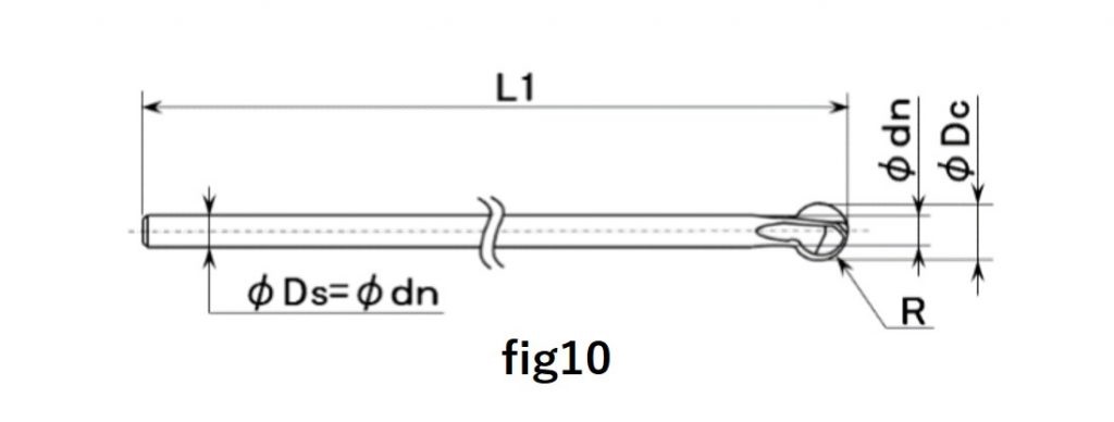
| Product code | Cutter radius R (mm) |
Cutter diameter Dc (mm) |
Neck diameter dn (mm) |
Overall length L1 (mm) |
Shank diameter Ds (mm) |
Number of blades | Fig |
| XC-18-B | 0.9 | 1.8 | 1.1 | 50 | 1.1 | 2 | 10 |
| XC-23-B | 1.15 | 2.3 | 1.4 | 60 | 1.4 | 2 | 10 |
| XC-28-B | 1.4 | 2.8 | 1.7 | 70 | 1.7 | 2 | 10 |
| XC-33-B | 1.65 | 3.3 | 2 | 80 | 2 | 2 | 10 |
| XC-38-B | 1.9 | 3.8 | 2.4 | 85 | 2.4 | 2 | 10 |
| XC-48-B | 2.4 | 4.8 | 3 | 105 | 3 | 2 | 10 |
| XC-58-B | 2.9 | 5.8 | 3.5 | 120 | 3.5 | 2 | 10 |
| XC-78-B | 3.9 | 7.8 | 4.7 | 150 | 4.7 | 3 | 10 |
| XC-98-B | 4.9 | 9.8 | 5.9 | 180 | 5.9 | 3 | 10 |
Applicable workpiece materials: Nonferrous metals, resin
| Product code | Cutter radius R (mm) |
Cutter diameter ΦDc (mm) |
Neck diameter Φdn (mm) |
Neck length L2 (mm) |
Overall length L1 (mm) |
Shank diameter φDs (mm) |
Number of blades | fig |
| XC-08-A-N | 0.4 | 0.8 | 0.48 | 5 | 60 | 3 | 2 | 9 |
| XC-13-A-N | 0.65 | 1.3 | 0.78 | 8 | 60 | 3 | 2 | 9 |
| XC-18-A-N | 0.9 | 1.8 | 1.1 | 10 | 60 | 3 | 2 | 9 |
| XC-23-A-N | 1.15 | 2.3 | 1.4 | 12.5 | 70 | 3 | 2 | 9 |
| XC-28-A-N | 1.4 | 2.8 | 1.7 | 15 | 70 | 4 | 2 | 9 |
| XC-33-A-N | 1.65 | 3.3 | 2 | 17.5 | 70 | 4 | 2 | 9 |
| XC-38-A-N | 1.9 | 3.8 | 2.4 | 20 | 70 | 4 | 2 | 9 |
| XC-48-A-N | 2.4 | 4.8 | 3 | 25 | 70 | 6 | 2 | 9 |
| XC-58-A-N | 2.9 | 5.8 | 3.5 | 30 | 70 | 6 | 2 | 9 |
| XC-78-A-N | 3.9 | 7.8 | 4.7 | 40 | 100 | 8 | 3 | 9 |
| XC-98-A-N | 4.9 | 9.8 | 5.9 | 50 | 120 | 10 | 3 | 9 |
XEBEC Tool Path includes a set of five tool paths corresponding to five different edge break lengths. Select an edge break amount depending on processing accuracy such as a hole diameter and position.
| Product code | Cutter dia. Dc (mm) |
Edge break amount (mm) | Allowable cumulative error (mm) |
||||
| ① | ② | ③ | ④ | ⑤ | |||
| XC-08-〇〇 | φ0.8 | 0.02 | 0.04 | 0.06 | 0.8 | 0.1 | 0.03 |
| XC-13-〇〇 | φ1.3 | 0.04 | 0.06 | 0.08 | 0.1 | 0.12 | 0.05 |
| XC-18–〇〇 | φ1.8 | 0.07 | 0.09 | 0.11 | 0.13 | 0.15 | 0.08 |
| XC-23–〇〇 | φ2.3 | 0.07 | 0.09 | 0.11 | 0.13 | 0.15 | 0.09 |
| XC-28–〇〇 | φ2.8 | 0.08 | 0.11 | 0.14 | 0.17 | 0.2 | 0.1 |
| XC-33–〇〇 | φ3.3 | 0.08 | 0.11 | 0.14 | 0.17 | 0.2 | 0.11 |
| XC-38–〇〇 | φ3.8 | 0.09 | 0.13 | 0.17 | 0.21 | 0.25 | 0.12 |
| XC-48–〇〇 | φ4.8 | 0.1 | 0.15 | 0.2 | 0.25 | 0.3 | 0.15 |
| XC-58–〇〇 | φ5.8 | 0.1 | 0.15 | 0.2 | 0.25 | 0.3 | 0.18 |
| XC-78–〇〇 | φ7.8 | 0.1 | 0.15 | 0.2 | 0.25 | 0.3 | 0.18 |
| XC-98–〇〇 | φ9.8 | 0.1 | 0.15 | 0.2 | 0.25 | 0.3 | 0.18 |
○XEBEC Back Burr Cutter is designed for NC machines. Never use it as a hand tool.
○Turn on advanced preview control of the machine tool helps to reduce errors in contouring the edges to be deburred.
○The processing error of the hole position must be kept as small as possible.