
I am Arai from the Research and Development Department.
In this article, I will explore why the XEBEC Burrless Chamfering Cutter enables high-feed chamfering of difficult-to-cut materials, focusing on its distinctive cutting-edge geometry and supporting experimental results. A closer look at the underlying principle reveals a structure strikingly similar to the winding roads of Irohazaka in Nikko, a mountainous area north of Tokyo in Tochigi Prefecture.
Product page: https://www.xebec-tech.com/en/products/xc/
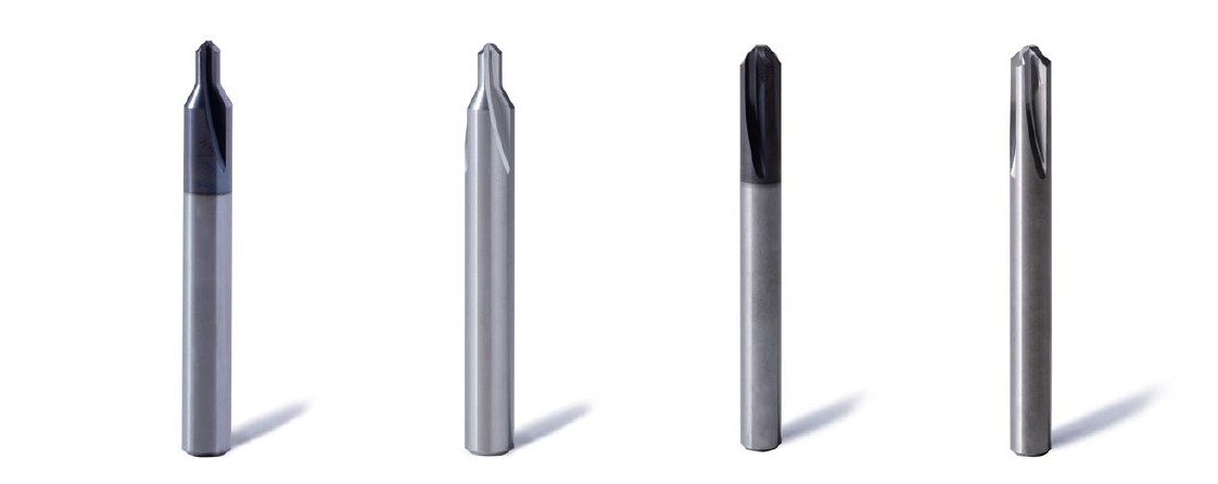
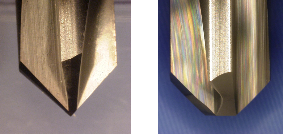
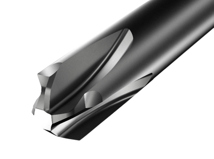
The XEBEC Burrless Chamfering Cutter adopts a V-shaped cutting-edge geometry. This shape suppresses the secondary burrs that tend to occur during chamfering, eliminating the need for a deburring process after chamfering.
This unique structure is patented, and its innovative design earned the XEBEC Burrless Chamfering Cutter Germany’s Best of Industry Award 2023.
The XEBEC Burrless Chamfering Cutter does more than suppress burr formation. Another key advantage is its ability to perform stable, high-feed chamfering on difficult-to-cut materials such as stainless steel, titanium, and Inconel.
So why can the XEBEC Burrless Chamfering Cutter machine difficult-to-cut materials at high feed rates while suppressing burrs?
First, difficult-to-cut materials are exactly what the name suggests: materials that are difficult to machine. Typical examples include the following:
These materials offer high performance as structural materials because they have excellent corrosion resistance, high strength, and heat resistance. For example, Inconel is used as a material for jet engine parts.

On the other hand, during machining, these materials tend to generate high cutting resistance. They may also harden during processing, and the heat generated is not easily dissipated. As a result, load and heat concentrate on the cutting edge of the tool, making wear and chipping more likely. For this reason, chamfering difficult-to-cut materials is a demanding cutting operation.
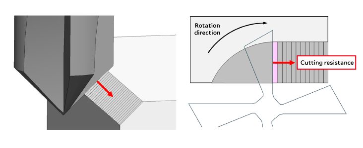
With a general straight-edge chamfering cutter, the portion of the edge used for chamfering contacts the workpiece almost simultaneously, so the cutting resistance rises all at once. Therefore, when the feed rate is increased on difficult-to-cut materials, problems such as edge chipping, chipping damage, and burr formation after chamfering are more likely to occur. As a result, there are many situations where machining conditions have to be reduced.
The situation is different with the XEBEC Burrless Chamfering Cutter. Even with the same difficult-to-cut material and the same chamfer size, it can perform stable machining at higher feed conditions compared with a straight-edge chamfering cutter.
The table below shows the recommended machining conditions for the XC-C-06-M when chamfering difficult-to-cut materials in sizes from C0.7 to C1.5.
| Chamfer size | Work material | Spindle speed (min⁻¹) | Feed speed (mm/min) | Feed per tooth (mm/t) |
|---|---|---|---|---|
| C1.0 | SUS | 4800 | 960 | 0.05 |
| C1.0 | Ti-6Al-4V | 4000 | 800 | 0.05 |
| C1.0 | Inconel | 2000 | 400 | 0.05 |
Recommended machining conditions for model XC-C-06-M (target chamfer size: C0.7-C1.5). Source: https://www.xebec-tech.com/en/howtouse/xc/
This shows that solid feed speeds are specified even for difficult-to-cut materials such as SUS, Ti-6Al-4V, and Inconel. So why are such conditions possible? The reason is that the way cutting resistance is applied is intentionally controlled.
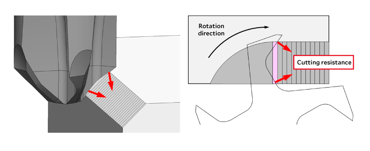
With the XEBEC Burrless Chamfering Cutter, only part of the V-shaped cutting edge contacts the workpiece at any given moment, and the contact point moves progressively along the edge. This prevents the cutting resistance from building up all at once in a single location. Instead, the load is distributed over both time and position.
Cutting in action (YouTube): https://www.youtube.com/watch?v=Vo9–ndfhIw
In addition, because the cutting edge acts diagonally, the cutting resistance applied to the cutting edge is less likely to concentrate in a single direction. Combined with the movement of the contact position, this makes it easier to distribute the load.
The important point here is that, for the same C-Chamfer, the actual volume of material being removed does not differ from that of a straight-edge chamfering cutter. What changes is the position and direction in which force is applied to the cutting edge. This difference is what allows the cutting edge to withstand high-feed machining.
How, then, does this difference appear in load data during actual machining? We compared a general straight-edge chamfering cutter with the XEBEC Burrless Chamfering Cutter (model: XC-C-06-M).
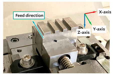
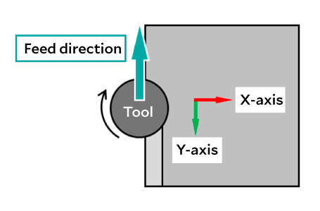
The edge of the workpiece shown below was chamfered in the direction indicated in the figure. The same machining conditions were used with the two types of chamfering cutters, and the load on the workpiece during machining was measured.
Machining conditions: spindle speed 6,300 min⁻¹, feed speed 1,260 mm/min, chamfer size C1.0, workpiece material medium-carbon steel (JIS: S50C).
When the chamfering cutter contacts the workpiece, the load rises in each axial direction. During machining, the load fluctuates finely because the cutting edge repeatedly contacts and leaves the workpiece. When the cutter exits the workpiece, the load can be seen returning to zero.
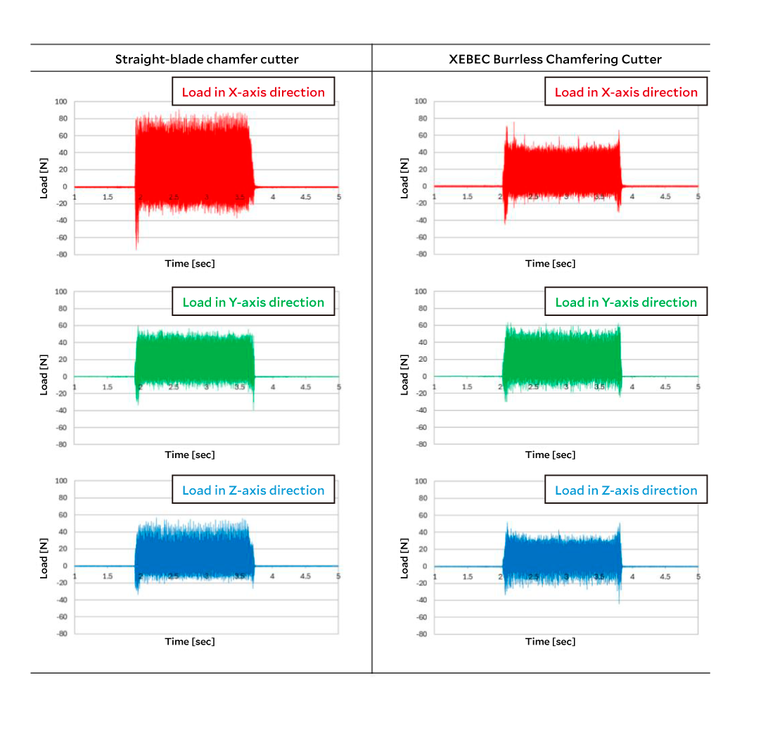
The chamfering section of the graph above is enlarged below. This enlarged view makes it easier to see the fine vibration pattern: the load rises at the moment the cutting edge contacts the workpiece and decreases when it leaves.
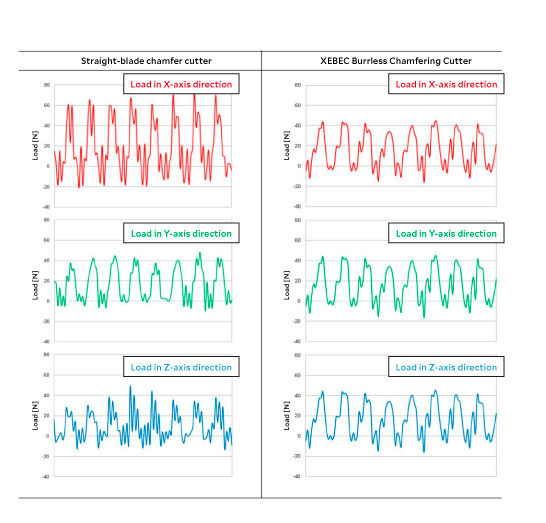
The point to focus on here is the vibration of the load in the X-axis direction. In this measurement, because chamfering was performed under the same machining conditions, there was no major difference in the average load value between the two chamfering cutters. However, in the X-axis direction, the straight-edge chamfering cutter showed larger vibration, while the XEBEC Burrless Chamfering Cutter kept the vibration amplitude smaller.
According to cutting theory, cutting force is considered to be strongly influenced by geometrical conditions such as the cross-sectional area of the material before it becomes chips. Therefore, if the same C-Chamfer is performed under the same machining conditions, the volume of material being removed is similar, and it is difficult for a large difference to appear in the average magnitude of the load itself. In fact, in this measurement as well, the difference in average load was small compared with the difference in amplitude.
On the other hand, as mentioned above, the vibration amplitude was larger with the straight-edge chamfering cutter, while the amplitude was greatly suppressed with the Burrless Chamfering Cutter. In other words, under the same machining conditions used in this comparison, the XEBEC Burrless Chamfering Cutter can be regarded as reducing load fluctuation compared with a straight-edge chamfering cutter. This experimental result aligns well with the state of cutting-edge contact explained in the previous sections.
As mentioned earlier, if the chamfer amount is the same for a straight-edge chamfering cutter and the XEBEC Burrless Chamfering Cutter, the amount being cut is the same. However, the position and direction of the force applied to the cutting edge differ.
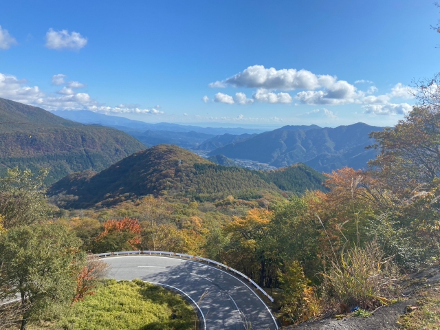
When thinking about this point—that the way force is applied changes—I was reminded of something. That was Irohazaka in Nikko City, Tochigi Prefecture.
Irohazaka is not a road that climbs a steep mountain in the shortest possible straight line. Instead, it is a winding mountain pass with a series of curves that repeatedly change the direction of travel while gradually gaining elevation.
As an aside, when I was a child, I drove Irohazaka countless times in a certain racing game. As an adult, I have also driven it in real cars and on motorcycles, and it remains one of my favorite roads.
Anyone who has driven along Irohazaka’s continuous hairpin bends knows that the road does not reduce the mountain’s overall elevation. However, compared with climbing the same slope in a straight line, the ascent feels far less demanding. Understanding why reveals a principle shared with the XEBEC Burrless Chamfering Cutter.
Whether the route is a steep straight road or a winding road like Irohazaka, the total elevation gained is the same. What changes is how that climb is distributed along the route.
First, on a straight steep road, the direction of travel is the same as the direction of the slope. For that reason, gravity continuously acts strongly in the same direction against the direction of travel, and a large force must be maintained in order to climb. This places a heavy load on the engine, the tires, and the driver.
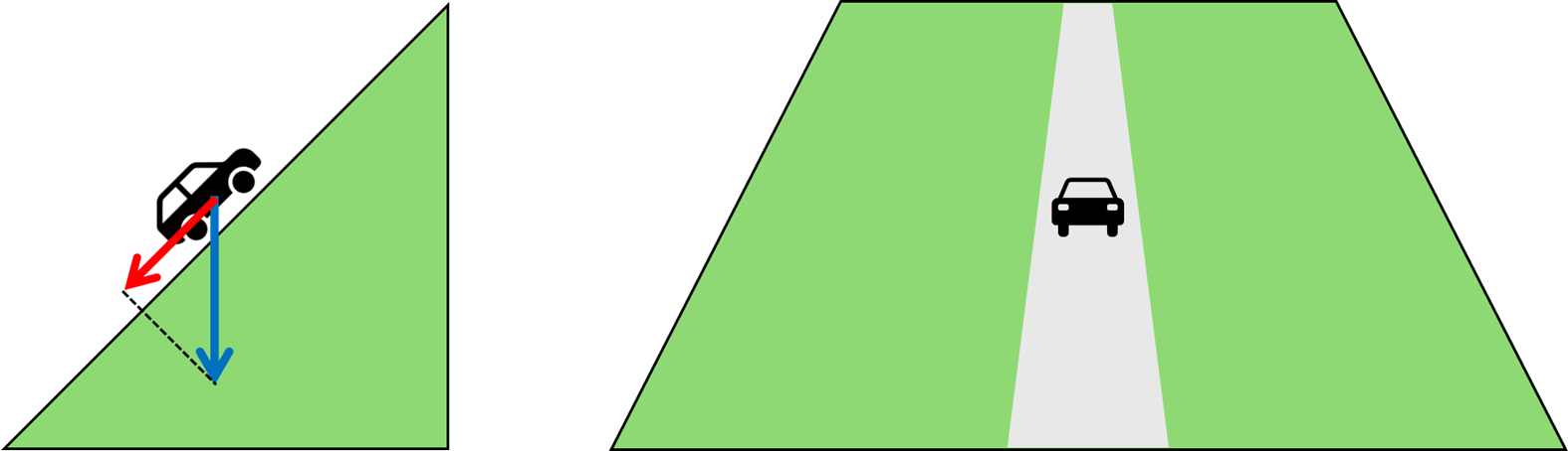
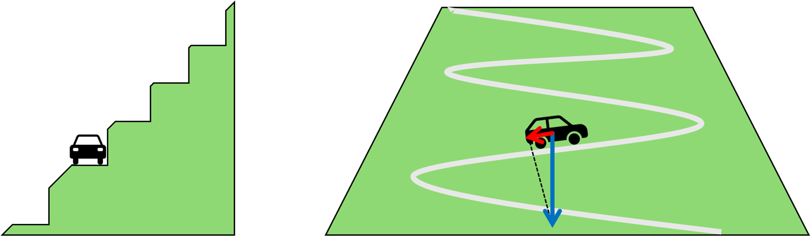
By contrast, on a winding slope, elevation is gained while the direction of travel changes repeatedly through curves. Even though the mountain gradient itself is the same, the car does not continue facing the slope head-on; it climbs while changing direction. This reduces the load that acts directly in the direction of travel, making it harder for a large burden to be applied all at once. As a result, the same elevation can be gained with far less strain than on a steep, straight road.
The same principle can be applied to chamfering tools.
With a general straight-edge chamfering cutter, the portion of the edge used for chamfering contacts the workpiece almost simultaneously. Therefore, cutting resistance rises at once and a large load concentrates on the cutting edge. Because the edge is straight, the cutting resistance acts on the cutting edge from almost a constant direction. This closely resembles climbing while facing the gradient head-on on a straight steep road.
Therefore, the relationship is: straight-edge chamfering cutter = a steep, straight road.
On the other hand, with the XEBEC Burrless Chamfering Cutter, the V-shaped cutting-edge geometry causes only part of the edge to make contact, and the contact point moves along the cutting edge. As the contact position moves, the position of the cutting resistance acting on the cutting edge is not fixed. Furthermore, because of the V-shaped geometry, the cutting resistance is decomposed diagonally, and the direction of the force applied to the cutting edge also changes continuously. This closely resembles the structure of a winding road, where the direction changes while climbing the slope and the load is not received all at once from the front.
Therefore, the relationship is: XEBEC Burrless Chamfering Cutter = the winding road structure of Irohazaka.
 |
 |
With either chamfering cutter, if the same C-Chamfer is being machined, the amount of material removed is the same. The difference is whether the force acting on the cutting edge concentrates in one place, or whether it is distributed while the position and direction change.
Just as Irohazaka is a road that allows a vehicle to climb an elevation difference without placing excessive strain on it, the XEBEC Burrless Chamfering Cutter can be described as a tool that allows machining to proceed without placing excessive strain on the cutting edge. Because cutting resistance is less likely to concentrate at one point, the load on the cutting edge is reduced. As a result, stable chamfering can be performed even on difficult-to-cut materials while setting a higher feed speed.
XEBEC Technology develops, manufactures, and distributes tools for automated deburring and chamfering of metal parts. Its innovations in the field of deburring include the world’s first ceramic fiber brushes and burrless chamfering cutters.
