Position the chamfering alignment diameter at chamfering center point of the workpiece. These must be aligned to prevent burring.
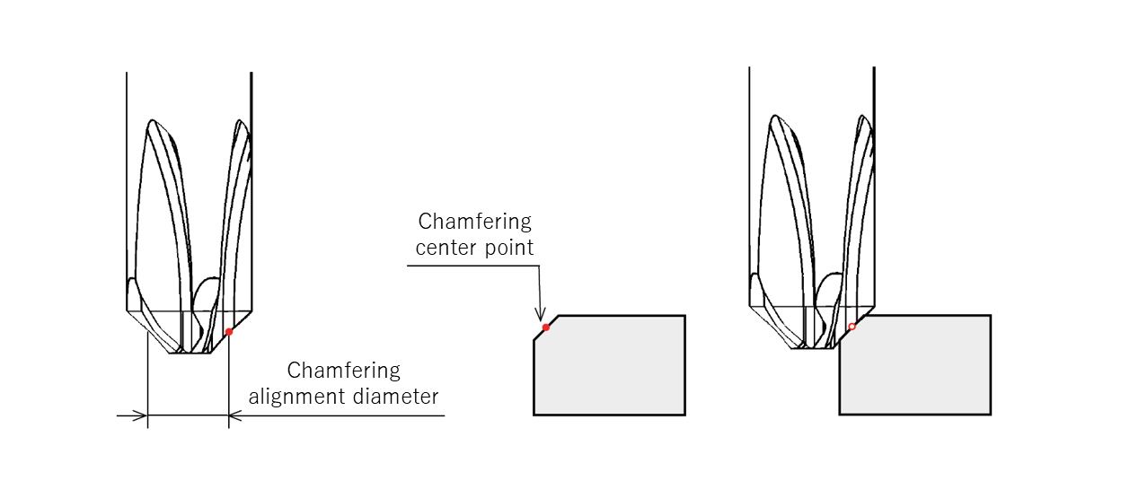
Create the machining program using Offsets A and B from the table for the desired chamfering size. This ensures the chamfer alignment diameter (Dc) and chamfer center point are aligned properly.
Formula for calculating Offsets A and B
・A=(Dc-C)/2
・B= (APMX+C) /2
*C = Chamfering size

| Chamfering size | Offsets (mm) | |
| A | B | |
| C0.3 | 0.85 | 0.65 |
| C0.4 | 0.8 | 0.7 |
| C0.5 | 0.75 | 0.75 |
| C0.6 | 0.7 | 0.8 |
| C0.7 | 1.65 | 1.35 |
| C0.8 | 1.60 | 1.40 |
| C0.9 | 1.55 | 1.45 |
| C1.0 | 1.50 | 1.50 |
| C1.1 | 1.45 | 1.55 |
| C1.2 | 1.40 | 1.60 |
| C1.3 | 1.35 | 1.65 |
| C1.4 | 1.30 | 1.70 |
| C1.5 | 1.25 | 1.75 |
| Product code | Workpiece material | Cutting speed | Rotational speed (min⁻¹) | Feed rate (mm/min) | Feed per tooth (mm/t) |
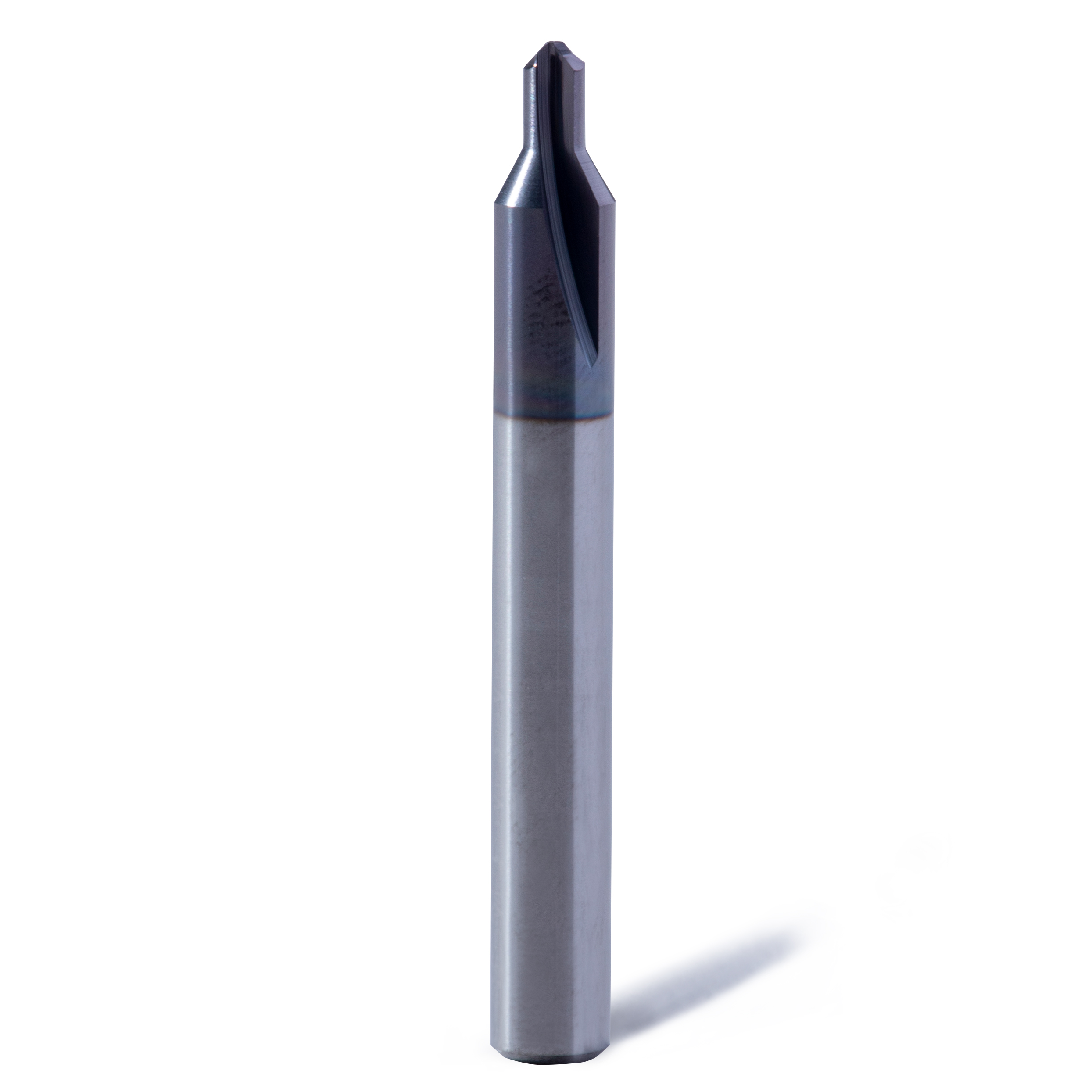
| XC-C-03-M | Steel | 60 – 100 | 12000 | 1800 | 0.05 |
| Stainless steel | 40 – 80 | 9000 | 1350 | 0.05 | |
| 64 titanium | 45 – 60 | 8000 | 1200 | 0.05 | |
| Inconel | 20 – 30 | 4000 | 600 | 0.05 | |
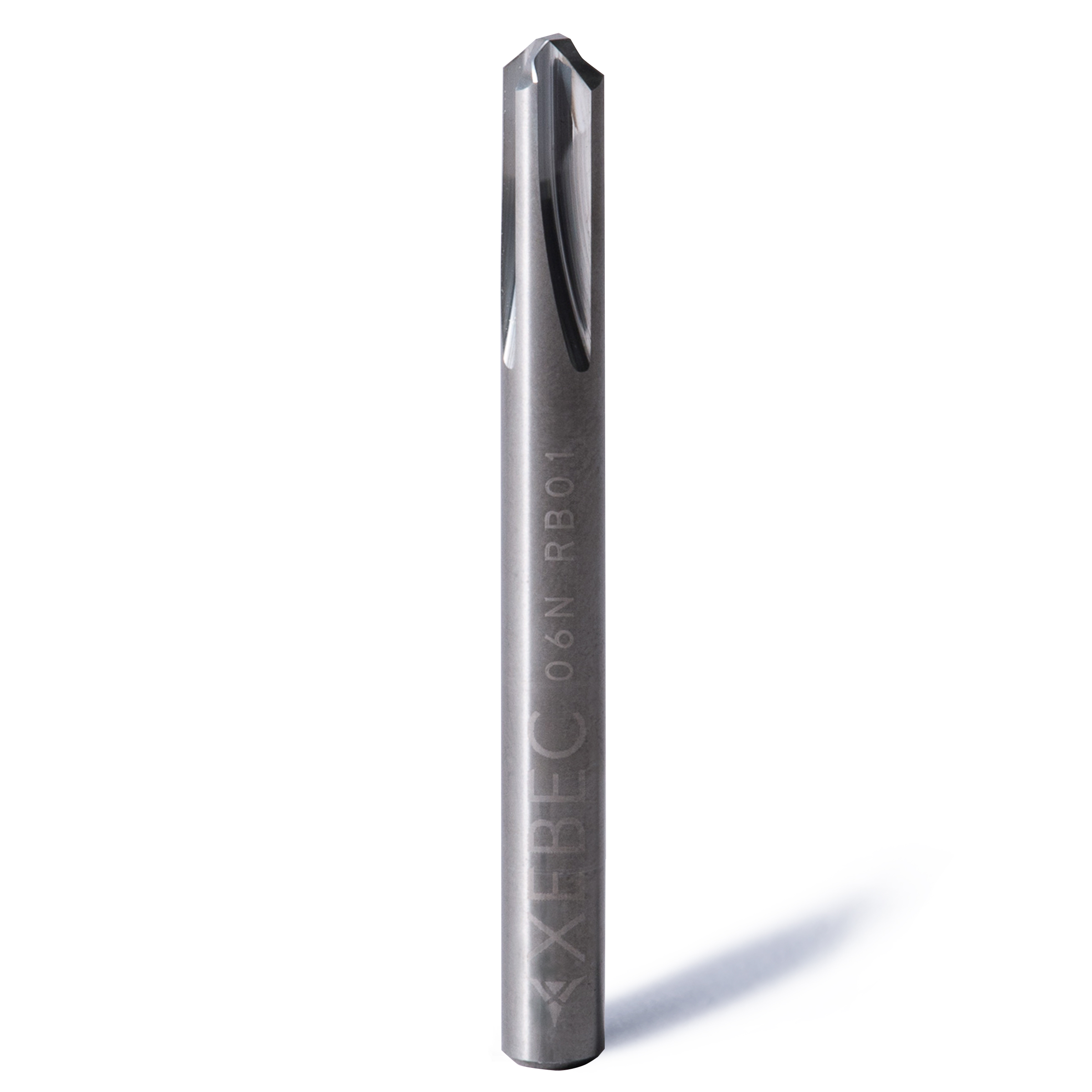
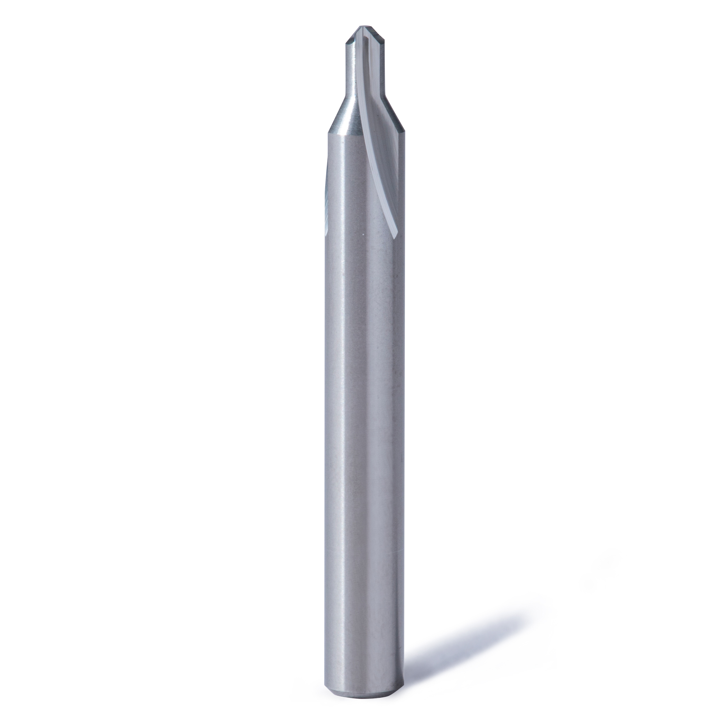
| XC-C-03-N | Aluminum alloy | 200 – 300 | 40000 | 6000 | 0.05 |
| Resin | 60 – 100 | 12000 | 1800 | 0.05 | |
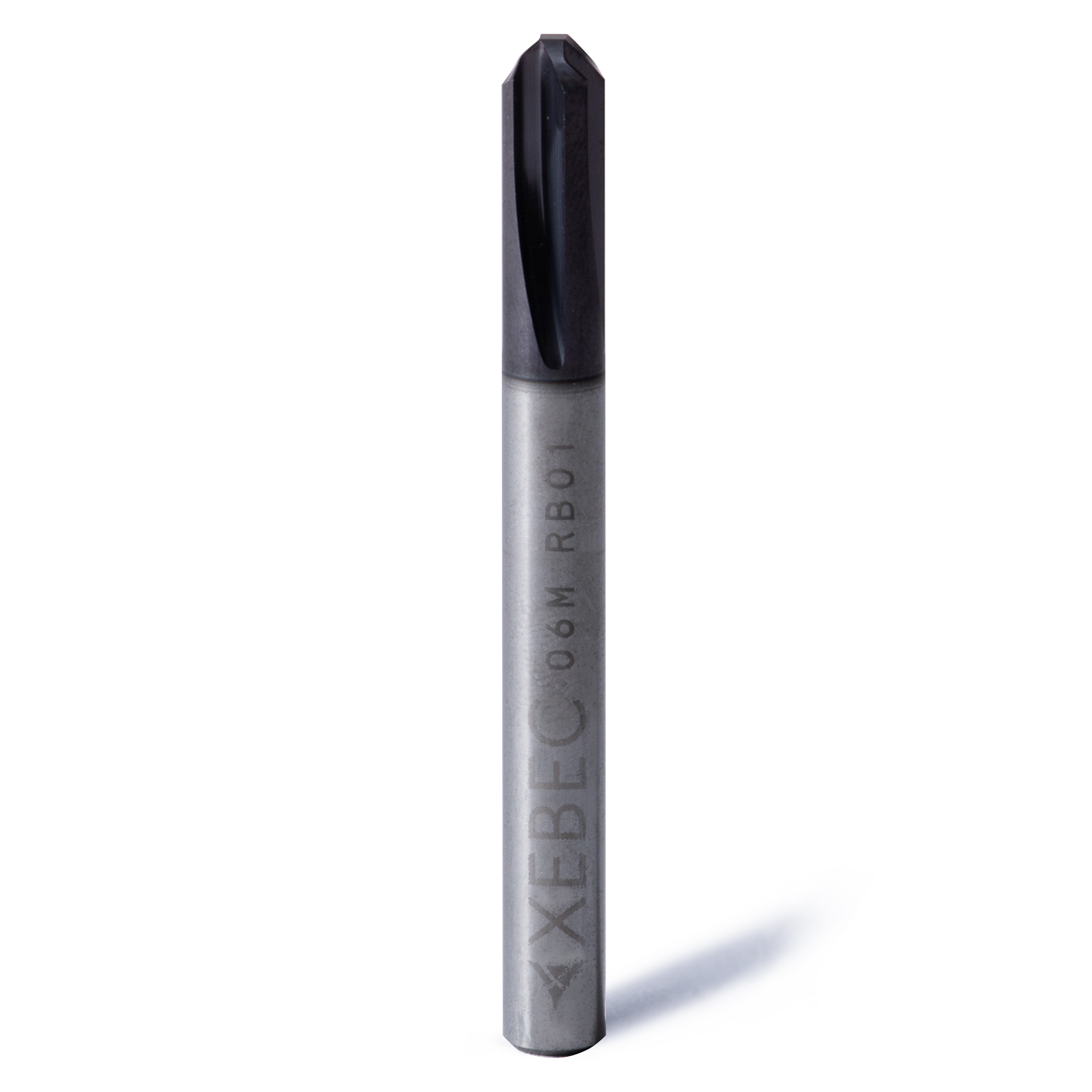
| XC-C-06-M | Steel | 60 – 100 | 6300 | 1260 | 0.05 |
| Stainless steel | 40 – 80 | 4800 | 960 | 0.05 | |
| 64 titanium | 45 – 60 | 4000 | 800 | 0.05 | |
| Inconel | 20 – 30 | 2000 | 400 | 0.05 | |
| XC-C-06-N | Aluminum alloy | 200 – 300 | 20000 | 4000 | 0.05 |
| Resin | 60 – 100 | 6300 | 1760 | 0.07 |
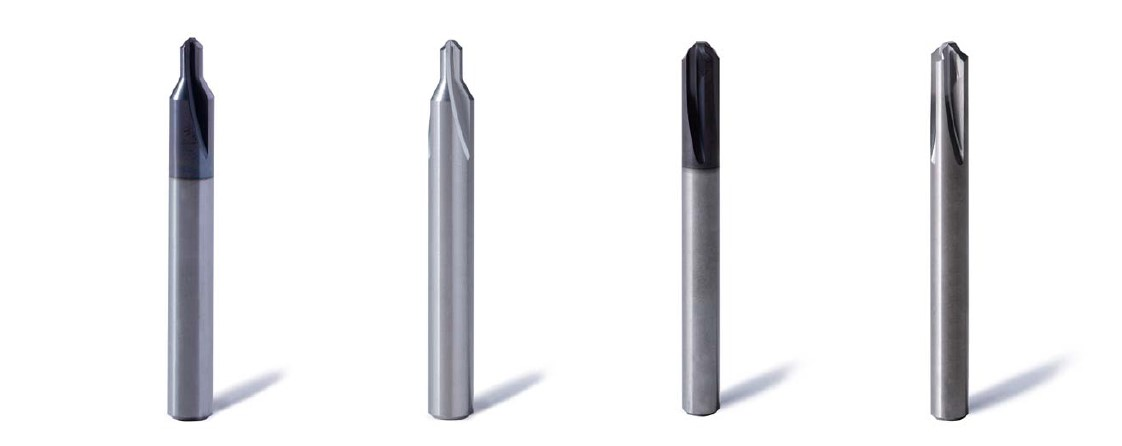
Burrless chamfering with the world’s first V-shaped blade