The tool can basically be used for workpieces that can be processed with XEBEC Brush Surface.
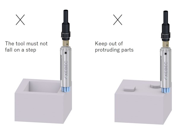
Avoid cavities and protrusions to ensure the floating function works properly.
When using the XEBEC Floating Holder, follow the usage instructions below.
FH-ST12-SL10 can be assembled in S40M-SD10 with shank dia. 10mm when bushing is not attached.
Also, S06M and S15M with shank dia. 6mm, and S25M and S40M with shank dia. 8mm can be assembled using the supplied special bush.
Align shank-fastening screw hole with bushing hole, insert special bushing as far as it will go, then secure the shank-fastening screw.
You can replace the spring to change the cutting load of FH-ST12-SL10 according to your desired machining quality.
Standard-load spring is built in when delivered.
The storage area of the spring is φ10.5 × 25 to 19 (6mm sliding).
Therefore, if the spring is φ10 and can be used in the range of 25mm to 19mm, it can be replaced.
In addition, we also offer springs whose load is higher than that of the high-load spring (0.72 to 1.05kgf), which maximum load of 1.52 to 3.34kgf. Please contact us for further details.
| Spring type | Outer diameter (mm) |
Spring constant (N/mm) |
Overall length (mm) |
Load by stroke (N) | ||
| 0mm | 6mm | |||||
| Standard spring | Installed | φ10 | 0.3 | 40 | 4.5 | 6.3 |
| Low-pressure spring | Attachment | φ10 | 0.3 | 30 | 1.5 | 3.3 |
| High-pressure spring | Attachment | φ10 | 0.55 | 39 | 7.2 | 10.5 |
| Maximum load spring | Sold separately | φ10 | 3.03 | 30 | 15.2 | 33.4 |
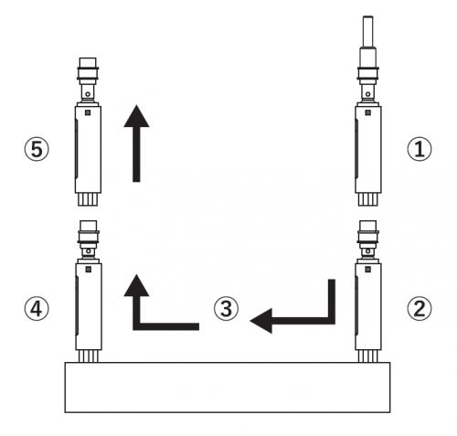
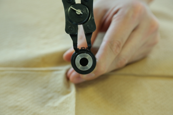
1. Remove the C-shaped retaining ring 2.
*Use the snap ring pliers for C type internal ring (C-shaped retaining ring size: 20mm)
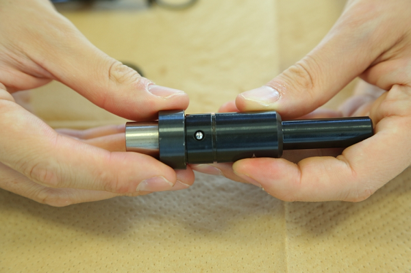
2. Remove the steel ball cap ring retaining the steel balls and take out the steel balls from the main unit. (2 locations)
*Be careful not to lose the steel balls as they are small.
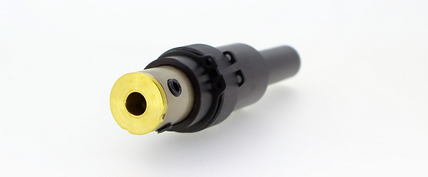
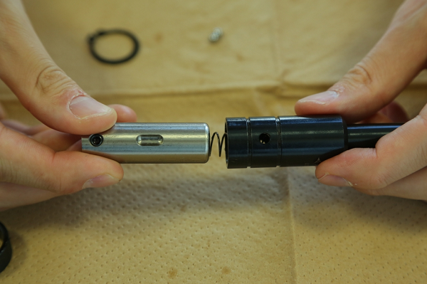
3. Remove the tool holding portion from the main unit and take out the spring.
Sparingly apply grease to the sliding portion (tool holding portion), re-attach the spring and return the sliding portion to the unit.
*Align the boat-shaped groove of the tool holding portion with the hole in the cap screw retaining the steel ball, which is on the main unit of the floating holder.
*Check that there is no dirt, etc. adhering within the tool holding portion or within the boat-shaped groove.
*Recommended grease : Lithium soap grease (NLGI # 2)
4. Insert the steel balls (2 locations), attach the steel ball cap ring retaining the steel balls, and then fit the C-shaped retaining ring 2 into the groove for this ring.
*Use only XEBEC-designated steel balls. Dangerous operation failure or tool damage may otherwise occur.
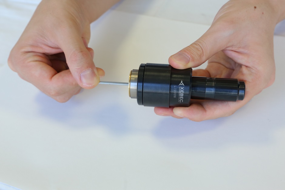
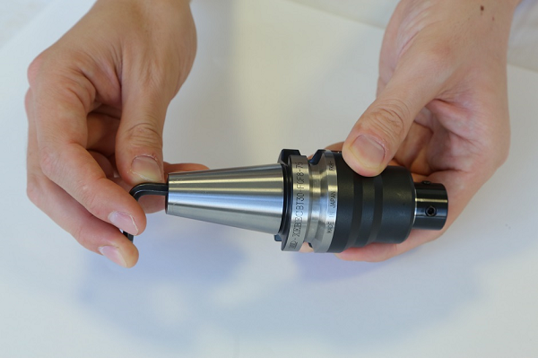
5. After assembling the parts, press the bottom of tool holding portion with your fingers, and check to see that tool holding portion slides 6mm.
Align the shank-fastening screw hole with bushing hole, insert the special bushing as far as it will go, then secure the shank-fastening screw.
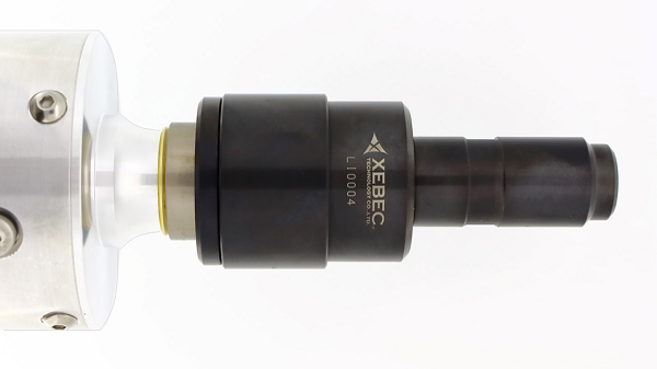
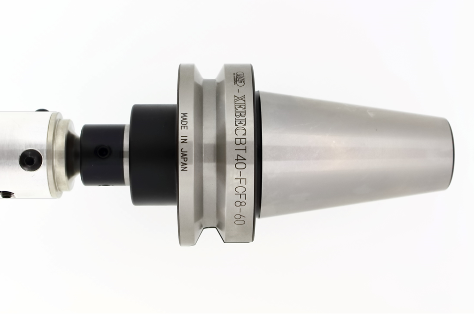
FH-ST20-60 is made for XEBEC Brush Surface of dia. 60mm with shank dia. 12mm.
FH-ST20-100 is made for XEBEC Brush Surface of dia. 100mm with shank dia. 16mm.
| Load adjustment | Load by stroke (N) | Adjustment screw position | |
| 0mm | 6mm | ||
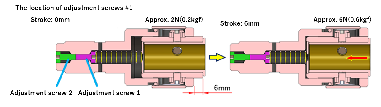
| Standard float | 2 | 6 | When load adjustment screw 2 is at the end of the shaft. |
| Higher float | 6 | 10 | When load adjustment screw 2 is at the back of the shaft. |
*Spring pressure is set to minimum when delivered.
The following drawing (the location of adjustment screw #1) shows when adjustment screw 2 is locked after it is loosened and adjustment screw 1 is tightened in the end.
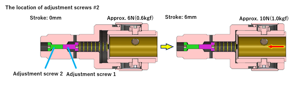
The following drawing (location of adjustment screw #2) shows when adjustment screw 1 is locked after it is loosened and adjustment screw 2 is tightened in the end.
| Load adjustment | Load by stroke (N) | Adjustment screw position | |
| 0mm | 6mm | ||
| Standard float | 2 | 6 | When load adjustment screw 2 is at the end of the shaft. |
| Higher float | 6 | 10 | When load adjustment screw 2 is at the back of the shaft. |
*Spring pressure is set to minimum when delivered.
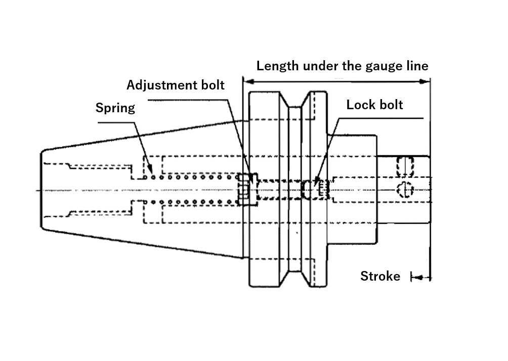
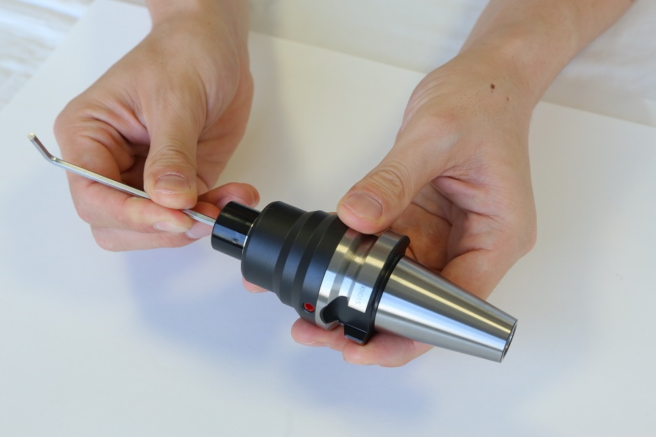
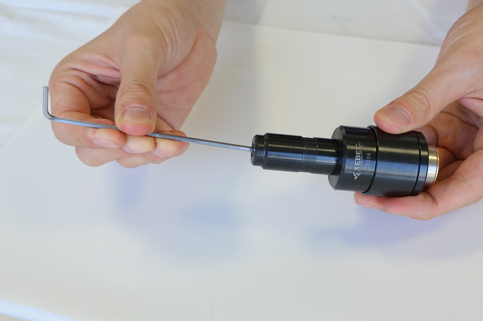
2. Remove the pull screw and move the adjustment screw to adjust the spring pressure, using a 5mm hexagonal wrench.
Minimum spring pressure is indicated when the adjustment screw is locked-off clockwise. Spring pressure is set to minimum when delivered.
Spring pressure increases as the adjustment screw is turned anti-clockwise. 6 full anti-clockwise turns will bring spring pressure to maximum.
Please be aware that more than 6 full turns will cause the spring to stick, hindering the floating function.
The built-in spring helps to maintain stable load, which enables consistent performance, while reducing the need to adjust the Brush projection length frequently.