A chamfer can be classified in one of three types: C-Chamfer, R-Chamfer, or Line Chamfer. The smallest type is a Line Chamfer. A Line Chamfer (also known as an edge break) typically does not have explicit size specifications. It is intended to remove burrs or break sharp edges. It does not have a functional purpose.
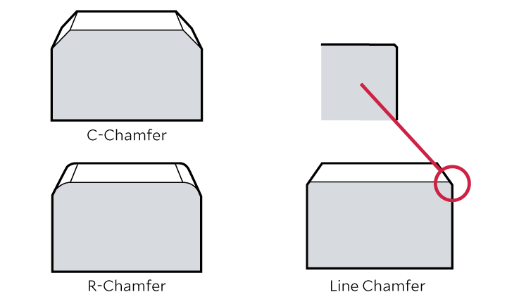
A Line Chamfer does not have to be a C-Chamfer. It could easily be an R-Chamfer if the purpose is merely to remove burrs from an edge. For example, when a file is used to remove burrs, the resultant shape is usually closer to an R-Chamfer than a C-Chamfer. Line Chamfers are usually finished to C0.2-0.3. In the case of large parts such as turbines, the C-Chamfer (or R-Chamfer) may be slightly larger. In other words, there are no hard-and-fast rules about the size of Line Chamfers. The lack of an explicit size on drawings creates ambiguity which may lead to an edge being finished somewhat differently from what was intended.
There should not be any ambiguity about the shape of parts in drawings. This is especially important nowadays where parts are often sourced from overseas. A machine shop in Mexico may supply parts to an assembly plant in the United States. Or a supplier in Turkiye may machine parts for a customer in Germany.
Both the understanding of machinists and commonly accepted practices vary in different countries. For a start, some countries are used to working in third-angle of projection (USA, Canada, Japan, United Kingdom, Australia). While others are used to working in first-angle of projection (Europe, India, East Asia).
Ambiguity about Line Chamfers is another source of potential confusion. Engineers in Japan may interpret a small chamfer or radius as being 0.2-0.3 mm. Engineers in the United States may interpret a small chamfer or radius as 0.005-0.015 inch (0.127-0.381 mm).
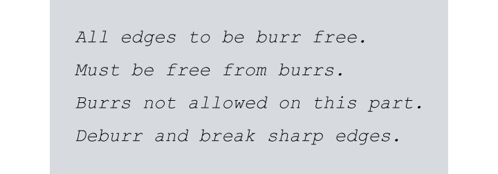
There are many ways to denotate a Line Chamfer on drawings. These qualitative instructions all mean the same and are equally ambiguous.
If the intention of the draftsperson were to be annunciated clearly, it would be something like the following:
Finish sufficiently to avoid problems with burrs. However, do not change the shape of the workpiece.
You may be wondering why no specific dimension is provided for a Line Chamfer.
If you were to add C0.2-0.3 to the edge where the Line Chamfer is required, you would have to mark the edge as C0.25 for dimensional accuracy. However, high accuracy requires more machining effort, which increases the cost of machining. Furthermore, the edge would have to measured and inspected to ensure the shape is as per the requirement on the drawing. Inspecting a small size chamfer such C0.2-0.3 involves considerable effort and cost. In other words, there is no need for dimensional tolerance on a Line Chamfer. It would just be a waste of time and expense.
However, qualitative instructions alone do not remove the inherent ambiguity of Line Chamfers. One solution may be to set a maximum chamfer size to give machinists a target without requiring precision cutting or measurement. For example, “Break all sharp edges 0.3 mm max”.
There are many ways to cut a Line Chamfer. Usually, the most efficient means for the given workpiece should be used. In the case of precision parts cut on a machining center, a small C-Chamfer can be added simply to the cutting program. This increases the cutting time of the machining center. However, the result is an accurate, controlled chamfer, with no additional machining required.
A milling machine may be used for machining large parts. The part would be clamped inside the machine and machined in stages to produce a C-Chamfer or R-Chamfer. The chamfer may be the only feature cut on the milling machine. For large parts with large production runs, using a separate machine for chamfering may improve overall productivity.
For large parts with small production runs or a complicated shape, it may be difficult to cut the chamfer on a milling machine. In this case, you have the option of using a file to deburr the edges by hand, using a special brush for deburring, or a special-purpose deburring machine.
XEBEC Technology recommends abrasive ceramic fiber brushes for breaking edges. These enable deburring to be carried out rapidly inside a machining center due to the high cutting power provided by using ceramic fiber instead of abrasive grain. These brushes are used in a wide range of automotive, aerospace, and medical applications.
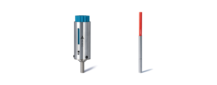
XEBEC Technology develops, manufactures, and distributes tools for automated deburring and chamfering of metal parts. Its innovation in the field of deburring includes the world’s first ceramic fiber brushes and burrless chamfering cutters.
