XEBEC Technology is a leading producer of tools for automated deburring and chamfering of metal parts. This is an introduction to the basics of chamfering. If you are familiar with chamfering, feel free to jump to Section 7 where a method of burrless chamfering is explained.
Index
・1. What is chamfering?
・2. Why is chamfering necessary?
・3. Types of chamfer
・4. Chamfering instructions
・5. How to chamfer
・6. Measurement of chamfers
・7. Chamfer tool selection
Chamfering is a post-machining process to remove sharp edges of a workpiece. If you have a metal case on your laptop computer or smartphone, try running your fingers around the edges. Of course, there is no chance of injury as the manufacturer ensures the edges are rounded and smooth through a chamfering or pressing process.
As mentioned above, one reason for chamfering is to prevent injury. Chamfering also makes parts easier to assemble, less prone to wear, and provides a better surface for joining. In other words, chamfering is an important aspect of good part design.
Metal parts will have sharp edges or burring when cut on a machine tool. This may injure someone handling or assembling them. The size of the chamfer required will depend on how the part is to be used. For example, a small chamfer is sufficient for normal handling. However, a more substantial chamfer would be required if there was any danger of an edge entering the eyes or mouth of a child.
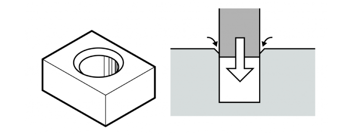
Parts may be chamfered to make them easier to assemble. For example, it is difficult to put a cylindrical rod in a round hole when the clearance is small.
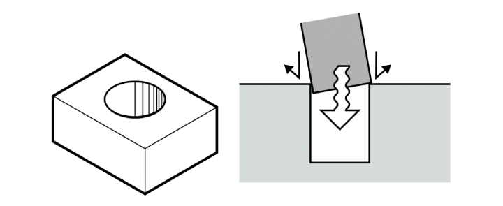
Assembly is easier if either the hole or rod have a chamfered edge which can act like a guide.
Sharp edges may break when frequently handled or moved. For example, a sharp edge may break off and become entangled in a mechanism. Chamfered edges are more resistant to wear and tear and less likely to break off.
Chamfered edges provide a better surface for welding or bolting together.
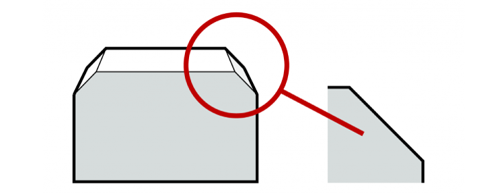
Broadly speaking, there are three types of chamfer: C-, R-, and Line Chamfers.
Also referred to as a Square Chamfer, this is the most common type of chamfer. A C-Chamfer involves creating a flat, angled surface, typically at a 45-degree angle to the edge. The resultant bevel is symmetric. A C-Chamfer is an effective means of preventing handling injuries and improving ease of assembly.
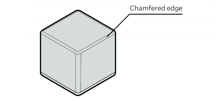
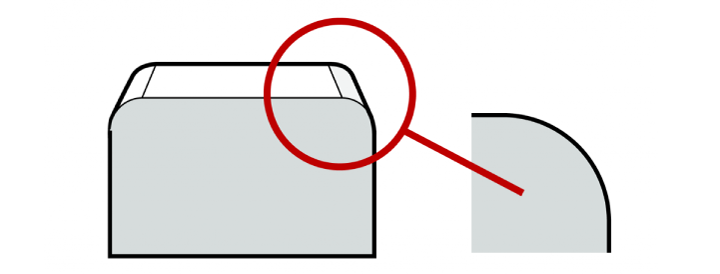
Also known as a Round Chamfer, this creates a smooth, curved transition between two surfaces. It is the most effective means of preventing handling injury and is also used to improve appearance.
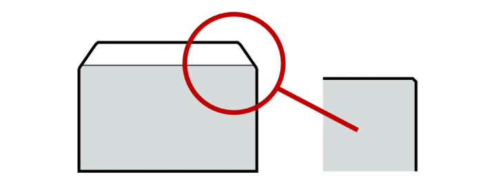
This is a very small chamfer often not visible to the naked eye. It is used to remove burrs and sharp edges. The chamfer width is extremely narrow, so it may not prevent all handling injuries.
Chamfering instructions on part drawings should be clear and precise. Here is how to specify chamfering instructions for the different types of chamfer.
C-Chamfer instructions are indicated by “Type and Size”, where size may be expressed as “Length and Angle”, “Length and Length”, or simply “Length”.
Length and Angle: This describes the chamfer size by its length and angle. For example, a chamfer shown as “C5 x 45°”, would be a 5mm chamfer at a 45-degree angle.
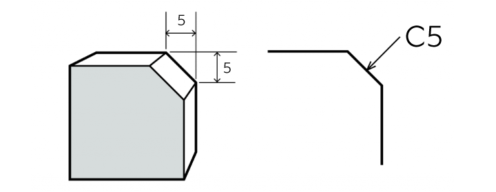
Length and Length: This describes the chamfer size by the length of its two sides. For example, a chamfer shown as “C5 x 5″, would also be a 5mm chamfer at a 45-degree angle.
Length: This is a simplified way to describe a 45-degree chamfer. For example, “C5” describes a chamfer with a 45-degree angle and two sides of 5mm.
The chamfering instruction comprises an arrow to indicate the edge to be chamfered, together with the chamfer type and size, as shown below right.
A general note on the drawing can be used to specify that all edges should have the same chamfer. For example, “All edges to be C5”. A single callout may also be used to indicate the number of edges requiring chamfering. For example, “10 x C5” would indicate there are ten edges that must be chamfered. Notes such as this help to reduce clutter in part drawings.
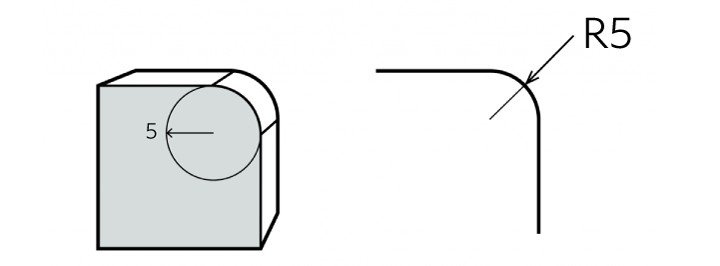
R-Chamfer instructions are indicated by “Type and Size”, where size indicates the radius of the chamfer. For example, an R-Chamfer shown as “R5” describes a 5mm radius. A general note such as “All edges to be R5” can be used for brevity.
Industrial standards such as ISO, JIS, and DIN do not provide specific instructions for Line Chamfers. It is common for drawings to include general notes for edges such as “No chamfer”, “Deburr all edges”, or “Break all sharp edges”. These represent the same thing i.e. a Line Chamfer.
Line Chamfers are usually thought of as C0.1-C0.3. It is advisable to use a general note such as “Line Chamfer C0.2 on all edges” in drawings if you want to avoid confusion.
Chamfering can be performed by turning, milling, drilling, or grinding.
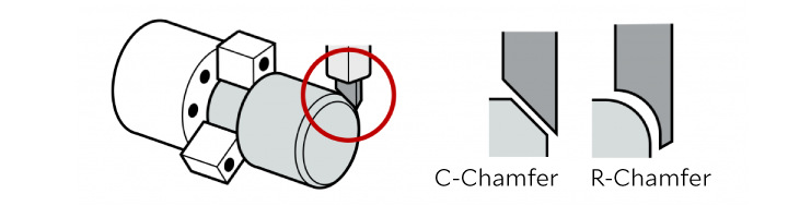
Turning is a process where a cutting tool is pushed against a rotating workpiece to remove material. The workpiece must be cylindrical as it is rotated at high speed.

Creating a chamfer with turning requires a 45-degree straight cutter to be used for C-Chamfers and an R-Cutter to be used for R-Chamfers.
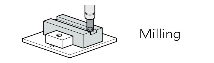
Milling is a process where a rotating cutting tool is pushed against a stationary workpiece to remove material. It is used to create complex shapes and contours in metal parts.
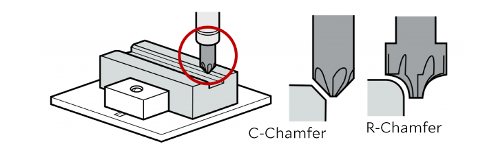
Creating a chamfer with milling requires a chamfer cutter for C-Chamfers and a corner rounding end mill for R-Chamfers. These tools are mainly used for chamfering flat surfaces.
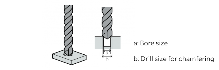
Bores are often chamfered by using a slightly larger drill than the bore diameter. This is the quickest way to chamfer a single hole. However, it may result in secondary burring, requiring an additional process with a spherical cutter to remove fine burrs.
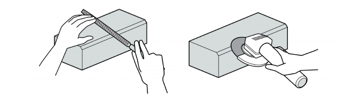
Chamfering can be performed manually with a disk grinder or file. It is difficult to produce an accurate chamfer by hand. Therefore, disk grinders and files are used mainly for Line Chamfering (deburring). An automated deburring process is recommended for consistent finish quality.
This section describes how to measure edges with C- or R-Chamfers. Line Chamfering is not a precision machining process, therefore it is excluded from consideration.
The face width of a C-Chamfer is measured using the hypotenuse of the chamfer.

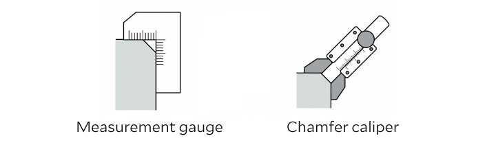
A chamfer measurement gauge or chamfer caliper is used to measure the dimensions of a C-Chamfer on metal parts.
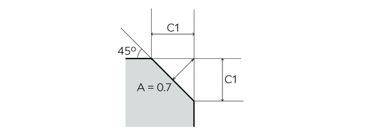
The depth of a 45-degree C-Chamfer is the distance from the original edge to the middle of the chamfer surface. If the chamfer is 45 degrees, the geometric properties of a right-angle, isosceles triangle can be used. If the sides of the chamfer are both 1mm, then:
Depth = C1 ÷ √2=0.707mm
The radius of an R-Chamfer is measured using a radial gauge, radius caliper, or CR caliper (chamfer and radius caliper).
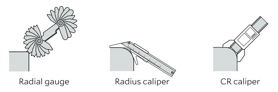
How to use a radial gauge: Find the leaf which fits the chamfer exactly.
How to use a radius caliper: Place calipers on the chamfer and read off the measurement.
How to use a CR caliper: Place calipers on the chamfer and read off the measurement. A CR caliper can measure both C-Chamfers and R-Chamfers.
The required chamfer type, size, angle, and positioning on the workpiece will determine which type of tool should be used. For example, the quickest way to satisfy a “break all edges” instruction may be to use a ceramic fiber brush.
Another consideration is the prevention of secondary burrs in the chamfering process. In the case of a milling process, secondary burring can be avoided by using a burrless chamfering cutter.
Milling with a straight chamfer cutter causes secondary burrs to form on the top and bottom edges as material pushed ahead of the blade flows off to the sides. The mechanism resembles the way a snowplow clears snow from a road. Snow builds up in front of the blade and flows off both sides.
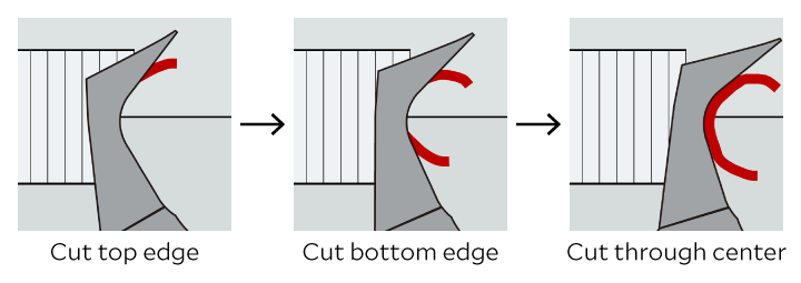
XEBEC’s solution (XEBEC Burrless Chamfering Cutter™) is a cutter with V-shaped blades that chamfers without creating secondary burrs, has twice the tool life of a straight chamfer cutter, and enables higher feed rates.
The first blade cuts the top edge of the material pushing it down toward the tool path. A second blade then cuts the bottom edge of the material pushing it up toward the tool path. Finally, a third blade cuts the material still attached in the center of the tool path and the chip is discarded. This mechanism eliminates secondary burrs on chamfered edges.