Type K: Orthogonal Cross Hole Aligned with X-axis (ar=90°/-90°)
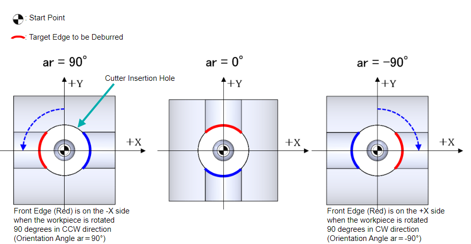
Assuming that the cross hole is aligned with the Y-axis (Orientation Angle ar=0°), Front Edge (Red) is defined as the edge that is on the +Y side and Rear Edge (Blue) is the edge on the -Y side as shown in the example below.
The relationship between Front (Red) /Rear (Blue) Edges and the orientation angle are also shown.
Example: Cross Hole Axis Aligned with X-axis
XEBEC Deburring Tool Path Specifications
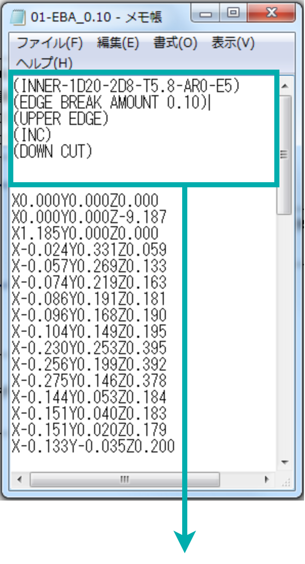
Specifications are indicated at the top of the text file in parentheses ( )
Specifications |
Descriptions |
|---|---|
| (INNER-1D8.-2D20.-T5.8.-AR90.-E3.) | INNER: Inner Edge [OUTER: Outer Edge] 1D8: Cross Hole 1D Diameter Φ8mm 2D20: Cutter Insertion Hole 2D Diameter Φ20mm T5.8: Cutter Diameter Φ5.8mm AR90: Cross Hole Orientation Angle 90° E3: Offset +3mm from the Cross Hole Axis |
| (EDGE BREAK AMOUNT 0.30) | Deburring Amount 0.30mm |
| (FRONT EDGE) | Front Edge [REAR EDGE: Rear Edge] |
| (INC) | Positioning Format: Incremental [ABS: Absolute] |
| (DOWN CUT) | Down Cut Machining [UP CUT: Up Cut Machining] |